This page addresses two key use cases:
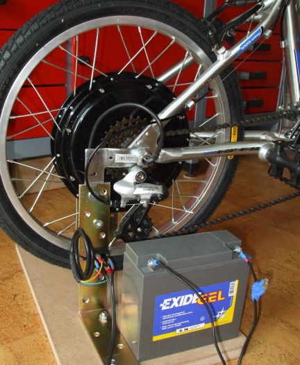
 This project fits a travel bike that will be taken to remote locations with no electricity. The user will be able to charge NiMH batteries for light, communication, navigation and entertainment equipment, utilizing the energy from the bike's standard 6V/3W dynamo. While riding, up to 6W of electrical power are available to the charger (not a mistake, it is about twice the rated dynamo power).
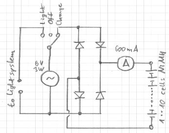
A switch selects either the light system, the battery charge mode or OFF. In charge mode, the rectified dynamo current is driven through a string of series-connected NiMH cells. At moderate riding speed, one to 10 cells can be charged at once. The current is typically 500mA and decreases somewhat as cell count increases. The ammeter displays the charge current, so it's easy to see if cells charge correctly and at the expected current.
All 4 diodes are 1N5402 (or 1N5404 through 1N5408). Alternatively, use 1N4003 through 1N4007 (lower current capability, higher chance of damage if reversing battery polarity).
If individual cells will be charged, an appropriate battery box is needed. A jumper cable makes the box adapt to fewer cells. It's acceptable to mix different types of cells; they will all be charged at the same current.
The circuit withstands operation without batteries connected. Batteries may remain attached to the circuit permanently, none of the modes produces a leakage current that discharges the cells. One weak point of the circuit is wrong battery polarity: This could fry the diodes and the ammeter. If batteries are likely to be reversed, a fuse should be added in line with the ammeter.
There is no end-of-charge indication as this would be unreliable with the fluctuating supply of a dynamo. Not a problem, cells get time to relax and cool down as the bike stops from time to time. With the rider being right there with his sense of time and his temperature probe finger, it's highly unlikely that batteries get forgotten and "cooked" for many hours. Much unlike cheap mains-powered chargers that overcharge NiMH cells by design - and still the cells last quite a while.
 This project is capable of providing basic electricity to a remote location where solar panels are not practicable. While pedaling, up to 300W are available (40 ..150 continuously, depending on rider).
The Internet holds a lot of suggestions on how to build a pedal-powered electrical generator. Now what has put ME off is that all these solutions require odd parts that are hard to come by and / or demand a lot of mechanical work in adapting a motor / generator to a bicycle. The end product often suffers from friction, belt slip and rapid wear.
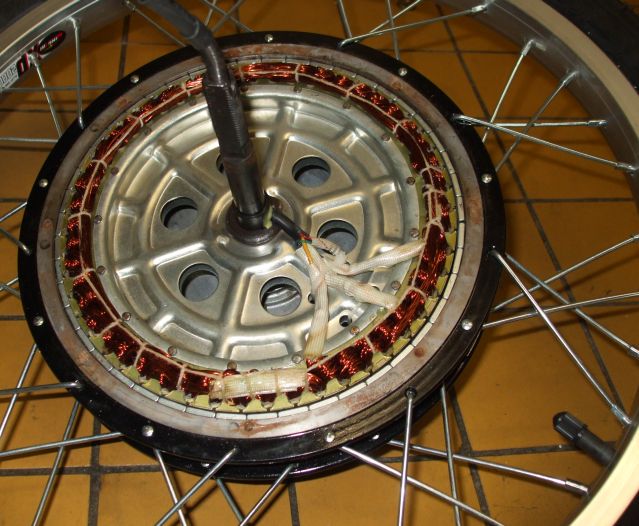
With the popularity of electric bicycles on the rise, the pedal generator builder's life has become easier: Today we have a good variety of bicycle hub motors, many of these made in Chinese factories and often being sold for less than EUR 100. These motors carry magnets on the rotor while the copper windings are on the stationary part. They are perfect dynamos !
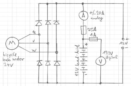
Now the rectifier output cannot directly power a lamp or a TV, as pedaling action is not producing a constant voltage. It will be fluctuating between 0 and way above the desired output voltage, likely doing damage to the equipment it feeds. The solution is to connect a battery across the rectifier output. This will absorb any extra power that the generator provides and it will fill the gap when the generator doesn't provide enough power or even stops for a short while. The battery doesn't have to be very big or special, any lead-acid battery is fine. If the battery is big (high Ah-rating), it's no harm though. For my own build, I've used an old 12V 16Ah computer backup battery. A sealed battery is recommended for indoor use, so that no gas can escape.
The schematic shows a few more components. One is the battery fuse. This part is mandatory because in case of short-circuit, the battery could drive such a high current that the cables go up in fire. I recommend 2.5sqmm cabling and a fuse of max 30A.
Finally there are two instruments in the circuit (not on the photo): One voltmeter (with its own fuse) and one ammeter. While the pedal generator will work without these instruments, the voltmeter is highly recommended for the sake of battery health. A digital voltmeter is best. As the instrument reads 14V (in a 12V system), the pedaling should be stopped. 15V should never be exceeded. The voltage also should not drop below 10.5V.
The ammeter is an analog zero-center instrument. While it's not essential, it indicates to the person pedaling if he's putting energy into the battery (eventually leading to a fully-charged battery) or if the load is drawing more current than the generator provides (leading to a discharged battery). A digital ammeter cannot be used here, as the current changes too much to allow for a stable reading.
The range of the ammeter depends on the current that will be drawn by the load and supplied by the generator (whatever is higher). I picked an instrument with a +/-20A range.
| When only the battery voltage is increased (nothing else changes) | -> | Higher cadence and lower force required to achieve same power output |
| When only the motor voltage increases (nothing else changes) | -> | Lower cadence and higher force required to achieve same power output |
| When only the chainring size increases (nothing else changes) | -> | Lower cadence and higher force required to achieve same power output |
| When only the sprocket size increases (nothing else changes) | -> | Higher cadence and lower force required to achieve same power output |
Practical approach to get it right: Pick motor voltage higher than battery voltage, then do the fine-tuning with sprocket and chainring (try different ratios). For this it is highly useful to have a bike with a working derailleur.
When charging a battery from its lowest voltage up to the maximum, the cadence increases throughout the charge process. Again, the capability to shift gears with the derailleur smoothes this out. Being able to run different gear ratios is also nice if different people (with different preferences) are using the pedal power generator.
My system specs: Motor 24V, battery 12V, chainring 42 tooth, sprocket 14 tooth (18 tooth below 11V battery voltage).