Dynamo-Powered LED Light Circuits for Bicycles
LED light systems offer exceptional reliability and superior light yield vs standard bicycle light systems. This is an evolutionary tutorial on how to power such systems from a dynamo. As you read, you will come across a variety of circuits that can be built at home.
BACK
A word about Power LEDs and Lumens
The following projects heavily use power LEDs. They are typically made by manufacturers such as Philips-Lumileds, Cree, Seoul Semiconductor. At the time of writing, these LEDs are subject of rapid improvement. In 6 months from now, a new model of power LED will probably make todays most advanced LEDs look dim. There could even be new manufacturers pushing on the market with superiour LEDs. Due to this, I never recommend any specific part number for the LEDs. The driver circuits are not affected by the type of LED used, as long as it has the typical forward voltage of a white LED.
You might want to know what sort of light output to expect from the circuits on this page. Well, you will only find LED power here. To know the Lumens, you have to download the datasheet of your LED of choice and look up how many Lumens it delivers for the Watts you feed it.
In order to build a bright light, you have to pay attention to three parts: The driver circuit (better if it delivers more power), the LEDs (better if they produce more Lumens per Watt), and the optics / reflectors / lens (better if their efficiency is closer to 100%).
Circuit 1 - a basic LED headlight
 |
| Position | Value | Alternative Value |
|---|
| D1 | 1N4007 | 1N5818 |
| D2 | 1N4007 | 1N5818 |
| D3 | 1N4007 | 1N5818 |
| D4 | 1N4007 | 1N5818 |
| LED1 | White Power LED (Luxeon, Cree..) |
|
Dynamo, bridge rectifier and a single power LED. This is all you need for an LED bicycle headlight !
How it works:
The AC from the dynamo passes a full-wave rectifier and feeds the single power LED of the headlight.
The LED current is reliably limited by the dynamo to about 500..600mA. Be sure that the LED can take this.
Silicon diodes (1N4007) do the job, while Schottky diodes (1N5818) minimze circuit losses.
This circuit works for both bottle dynamos and hub dynamos. It produces a little over 1.5W of LED power.
Above circuit has one little issue: The light flickers at low speed, particularly if powered from a hub dynamo. Here's what to do about it:
Circuit 2 - less flicker at low speed
 |
| Position | Value | Alternative Value |
|---|
| D1 | 1N4007 | 1N5818 |
| D2 | 1N4007 | 1N5818 |
| D3 | 1N4007 | 1N5818 |
| D4 | 1N4007 | 1N5818 |
| C1 | 1,000 .. 10,000uF @ min.4V |
| LED1 | White Power LED (Luxeon, Cree..) |
|
A smoothing capacitor reduces flicker at low speed and generally adds a tiny little bit of brightness. The higher the capacitance value of C1, the less flicker.
C1 needs to withstand at least 4V and there's no upper limit to its capacitance. Well, cost and size are somewhat limiting factors.
The circuit works both for hub and bottle dynamos while hub dynamos require a larger capacitor to reduce the flicker.
A word of caution: C1 should be mounted inside the headlight enclosure where it must be properly connected to the LED. Should the LED disconnect from the circuit, C1 charges to a rather high voltage (can be 100V when going fast). This could not only be dangerous to a person's health but upon reconnection to the LED, a dramatic peak current most likely decolors or destroys the LED. This is valid for most circuits on this page.
If you prefer to use a battery-powered tail light, skip this section
Circuit 3 - a basic tail light added to the headlight
 |
| Position | Value | Alternative Value |
|---|
| D1 | 1N4007 | 1N5818 |
| D2 | 1N4007 | 1N5818 |
| D3 | 1N4007 | 1N5818 |
| C1 | 1,000 .. 10,000uF @ min.4V |
| LED1 | White Power LED (Luxeon, Cree..) |
| LED2 | Red Power LED or min.15x SMD-LED |
|
The tail light LED takes the place of one of the rectifier diodes. Consequently, it's driven at half the current of the headlight LED. With red LEDs having about half the forward voltage of white LEDs, the tail light power is 25% of the headlight power.
The use of multiple red low-power LEDs (e.g. 15x Osram LS T676) in a parallel connection is an alternative to a power LED.
Any tail light LED has to withstand 5V of reverse-voltage.
To turn the tail light off, shunt it with a rectifier diode.
Circuit 4 - an alternative tail light
 |
| Position | Value |
|---|
| D1 | 1N4007 |
| D2 | 1N4007 |
| D3 | 1N4007 |
| D4 | 1N4007 |
| C1 | 1,000 .. 10,000uF @ min.4V |
| R1 | 47R 0.25W |
| LED1 | White Power LED (Luxeon, Cree..) |
| LED2..5 | Red SMD LEDs (Osram LS T676) |
|
Now here's an alternative way to connect a tail light. Unlike circuit 3 where the tail light power is 25% of the headlight power, it is now adjustable by R1. With this, it is possible to dim the tail light to a current low enough to be taken by a few SMD-LEDs.
Another interesting feature is this: The tail light is directly wired to the dynamo terminals, so that a cable that may already be there from a traditional bicycle light can remain attached to the dynamo.
Disadvantages of circuit 4 are the need to define a resistor value, the lower brightness of the tail light and the fact that the tail light is damaged should the headlight disconnect.
In the partlist above, a value of 47 Ohm is suggested for R1. The actual value depends on the LEDs used. It's best to build it and measure the tail light current, then correct the value of R1 if a lower or higher LED current is desired. The reverse-voltage of the LEDs is unritical in this circuit.
To turn this tail light off, disconnect it.
Circuits 5 & 6 - a tuning capacitor increases the power at moderate speed
Circuit 2 for reference
|
Circuit 5
 |
What is the difference between circuit 2 and circuit 5 ? Capacitor C2 has been added between the dynamo and the rectifier.
See how this affects the LED power vs speed curve, as the value of C2 varies:
While there's not a big difference at very low and very high speed, the boost in the middle is real nice to have.
Unfortunately, this comes at a price: C2 has to be a non-polarized part and its value is somewhat critical. With a typical bottle dynamo C2 = 220uF works well, with a hub dynamo its capacity would have to be a monstrous 1500uF. The required non-polarized capacitor can be hard to find, real large and somewhat expensive. Circuit 6 gets around this by using two regular (polarized) capacitors instead. Each of these has twice the capacity and should be a low-ESR type, as typically used in switchmode power supplies. Resistor R1 is uncritical, it merely biases C2 and C3.
Circuit 6
|
| Position | Value for bottle dynamo | Value for hub dynamo |
|---|
| D1 | 1N5818 | 1N5818 |
| D2 | 1N5818 | 1N5818 |
| D3 | 1N5818 | 1N5818 |
| D4 | 1N5818 | 1N5818 |
| C1 | 2,200uF @ min.4V | 10,000uF @ min.4V |
| C2 | 470uF 63V low-ESR | 3300uF 35V low-ESR |
| C3 | 470uF 63V low-ESR | 3300uF 35V low-ESR |
| R1 | 47K 0.25W | 47K 0.25W |
| LED1 | White Power LED (Luxeon, Cree, ..) |
|
Circuit 7 - driving more than one LED
The dynamo is more or less a constant current source, so when connecting two LEDs in series, the total power output of the system (nearly) doubles. Why not connect 3, 4 or more LEDs in series ?
To make the best of it, the tuning capacitors from circuit 6 have been maintained.
Depending on how many LEDs and what type of dynamo are used, the component values vary widely. Refer to these tables:
| Bottle Dynamo |
|---|
| | 1 LED | 2 LEDs | 3 LEDs | 4 LEDs |
|---|
| Total Power | 1.6 W | 3.0 W | 4.6 W | 5.8 W |
|---|
| D1..D4 | 1N5818 | 1N5818 | 1N5818 | 1N5818 |
| C1 | 2200uF 4V | 2200uF 10V | 2200uF 16V | 2200uF 16V |
| C2, C3 | 470uF 50V | 220uF 63V | 100uF 100V | 47uF 100V |
| R1 | 47K 0.25W | 47K 0.25W | 47K 0.25W | 47K 0.25W |
| LED1 | Power LED | Power LED | Power LED | Power LED |
| LED2 | N/A | Power LED | Power LED | Power LED |
| LED3 | N/A | N/A | Power LED | Power LED |
| LED4 | N/A | N/A | N/A | Power LED |
|
| Hub Dynamo |
|---|
| | 1 LED | 2 LEDs | 3 LEDs | 4 LEDs | 6 LEDs |
|---|
| Total Power | 1.6 W | 3.4 W | 5.2 W | 6.7 W | 10.5 W |
|---|
| D1..D4 | 1N5818 | 1N5818 | 1N5818 | 1N5818 | 1N5818 |
| C1 | 10,000uF 4V | 4700uF 10V | 4700uF 16V | 4700uF 16V | 2200uF 25V |
| C2, C3 | 3300uF 35V | 1500uF 35V | 1000uF 63V | 470uF 100V | 220uF 100V |
| R1 | 47K 0.25W | 47K 0.25W | 47K 0.25W | 47K 0.25W | 47K 0.25W |
| LED1 | Power LED | Power LED | Power LED | Power LED | Power LED |
| LED2 | N/A | Power LED | Power LED | Power LED | Power LED |
| LED3 | N/A | N/A | Power LED | Power LED | Power LED |
| LED4 | N/A | N/A | N/A | Power LED | Power LED |
| LED5 | N/A | N/A | N/A | N/A | Power LED |
| LED6 | N/A | N/A | N/A | N/A | Power LED |
|
A Busch & M�ller Dymotec6 bottle dynamo (8 magnetic poles) and a Shimano DH-3D71 hub dynamo (28 magnetic poles) were used to determine these values. Different dynamos of the same type are expected to perform very similar. Please check if YOUR dynamo contains a zener diode that is intended to limit the output voltage for use with light bulbs. If so, you need to remove it.
Now enjoy the power curves below. It's amazing, a 3W hub dynamo can feed more than 10W into a string of LEDs ! Well, again this doesn't come for free. Whenever you get out more, you are putting in more energy with your legs.
Note that the higher output curves not just require more calories to be put in, they also produce very little light at low speed. A 6 LED hub system e.g. puts out zero light at 8 km/h, something that is often not acceptable. Why not jump to a different curve at low speed ? Read on.
Circuit 8 - inclusion of a voltage doubler
Circuit 7, when used with a higher number of LEDs, suffers from poor power at low speed. This can be seen from the power curves above. Should it be an issue for you, there are several ways to address this:
- Some of the LEDs can be bypassed and different tuning capacitors be switched in, so the circuit can be changed into one with fewer LEDs that performs better at low speed.
- Parallel installation of let's say a 6-LED and a 3-LED version. A switch selects the one that is more appropriate. The 6-LED light engine could have a narrow beam for far projection while the 3-LED light engine would have a wider beam for lower speed.
- Switching the bridge rectifier to a voltage doubler, making the circuit behave like one that has half the number of LEDs.
Solution 1 requires complex switching and appears odd with some of the LEDs off. Solution 2 is probably the ultimate one but requires extra LEDs and optics. Still it is straightforward to build. Solution 3 adds little cost and complexity, while running all LEDs no matter what mode. This is the one I will go into here.
What you see here is circuit 7 redrawn and a Greinacher voltage doubler on the right. Circuit 8 below combines both in one. A simple switch changes between the two modes.
This circuit (minus R1, C2, C3) used to be popular in computer power supplies. On the primary side, it accomplished the 115/230 V selection.
Here's the list of component values for different configurations of circuit 8. Single and dual LED systems are not covered, as their low-speed performance is naturally good and circuit 7 is sufficient.
| | Bottle Dynamo | Hub Dynamo |
|---|
| | 3 LEDs | 4 LEDs | 3 LEDs | 4 LEDs | 6 LEDs |
|---|
| Total Power | 4.6 W | 5.7 W | 5.2 W | 6.7 W | 10.5 W |
|---|
| D1..D4 | 1N5818 | 1N5818 | 1N5818 | 1N5818 | 1N5818 |
| C1 | 2200uF 16V | 2200uF 16V | 4700uF 16V | 4700uF 16V | 2200uF 25V |
| C2, C3 | 100uF 100V | 47uF 100V | 1000uF 63V | 470uF 100V | 220uF 100V |
| C4, C5 | 100uF 63V | 47uF 63V | 470uF 35V | 470uF 35V | 220uF 63V |
| R1 | 47K 0.25W | 47K 0.25W | 47K 0.25W | 47K 0.25W | 47K 0.25W |
| SW1 | 120VAC 2A | 120VAC 2A | 120VAC 2A | 120VAC 2A | 120VAC 2A |
| LED1 | Power LED | Power LED | Power LED | Power LED | Power LED |
| LED2 | Power LED | Power LED | Power LED | Power LED | Power LED |
| LED3 | Power LED | Power LED | Power LED | Power LED | Power LED |
| LED4 | N/A | Power LED | N/A | Power LED | Power LED |
| LED5 | N/A | N/A | N/A | N/A | Power LED |
| LED6 | N/A | N/A | N/A | N/A | Power LED |
|
|
These are the performance curves. The lower curve of each color is the voltage doubler mode. Note how this mode is superior at low speed while above a certain speed, the bridge rectifier mode wins. The ideal cross-over frequency can be read from the second graph.
Let's look at some interesting variations of circuit 8:
Circuit 9 - a variation of circuit 8
|
|
Above circuit has the same performance and nearly the same partlist as circuit 8. The main difference is the switch: It not only selects between low speed mode (doubler) and high speed mode (bridge rectifier), it also has an OFF position which is very useful when powering the light from a hub dynamo. SW1 is a 1P2T switch with an isolating center position. These switches are commonly available.
Another feature of circuit 9 is the tail light. Unlike in circuit 8, LED1 is red.
Circuit 10 - one more variation of circuit 8
|
| | Bottle Dynamo | Hub Dynamo |
|---|
| | 3 LEDs | 4 LEDs | 3 LEDs | 4 LEDs | 6 LEDs |
|---|
| Total Power | 4.6 W | 5.7 W | 5.2 W | 6.7 W | 10.5 W |
|---|
| D1..D4 | 1N5818 | 1N5818 | 1N5818 | 1N5818 | 1N5818 |
| C1 | 2200uF 16V | 2200uF 16V | 4700uF 16V | 4700uF 16V | 2200uF 25V |
| C2, C3 | 100uF 100V | 47uF 100V | 1000uF 63V | 470uF 100V | 220uF 100V |
| R1 | 47K 0.25W | 47K 0.25W | 47K 0.25W | 47K 0.25W | 47K 0.25W |
| SW1 | 120VAC 2A | 120VAC 2A | 120VAC 2A | 120VAC 2A | 120VAC 2A |
| LED1 | Power LED | Power LED | Power LED | Power LED | Power LED |
| LED2 | Power LED | Power LED | Power LED | Power LED | Power LED |
| LED3 | Power LED | Power LED | Power LED | Power LED | Power LED |
| LED4 | N/A | Power LED | N/A | Power LED | Power LED |
| LED5 | N/A | N/A | N/A | N/A | Power LED |
| LED6 | N/A | N/A | N/A | N/A | Power LED |
|
Circuit 10 eliminates 2 of the 4 tuning capacitors but instead adds a more complex switch. This is useful if large capacitors are required while space is tight.
Similar to circuit 9, a switch with an isolating center position may be used so that the light can be switched off.
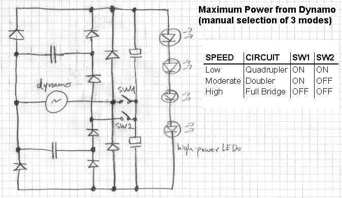
Circuit 11 - the voltage quadrupler
If you like to dig a bit deeper into the concept of voltage multiplication, check out my draft of a combined doubler / quadrupler / bridge rectifier.
Circuits 8 to 10 achieve high power while still maintaining reasonable brightness at low speed. This is accomplished by switching the bridge rectifier to a voltage doubler when going slow. While this works well, it requires constant user interaction. Some users may like this sort of control, as it enables them to run the light on low while going fast. Most users however just want the maximum light output they can get and rather not mess with the modes of their light while riding. They need automatic switching. It can be done in two ways:
- Mechanical coupling of the switch to the shifter / the shifter cable. Depending on the gear chosen, the light operates either in doubler mode (low gear) or in bridge rectifier mode (high gear).
- A speed switch reading the dynamo frequency selects doubler mode at low speed. This is what circuit 12 does.
Circuit 12 - automatic mode selection
Circuit 12 boasts automatic switching between modes. It consists of 3 basic parts:
- Power stage: Dynamo, rectifier / doubler, tuning capacitors, LEDs, MOSFET switches Q1 & Q2 with their drivers Q3 & Q4
- Overvoltage crowbar T1, D5, R17
- Speed switch IC1 (LM2907) with mode indicator LD11 and hysteresis switch Q5
Again, the power stage is being switched between bridge rectifier and voltage doubler just like in circuit 8. Due to the specific requirements of the MOSFET switches, it's not exactly the same circuit but it does the same and it performs the same.
The LED string stabilizes the voltage for the speed switch IC1 and the overvoltage crowbar is there to short out and thereby protect the circuit should the LEDs accidentially disconnect.
The speed switch IC1 contains a freqency-to-voltage converter (f2V) and a comparator. The input of the f2V block is the AC waveform from the dynamo. The switching frequency is set by R15. The output transistor of IC1 controls the base current of the MOSFET driver transistors Q3 and Q4 as well as the indicator LD11.
Q5 slightly shifts the reference voltage of the comparator to induce some hysteresis. This is needed to avoid instability near the switching point.
Circuit 12 achieves the same power curves as circuit 8 and it can drive from 3 to 8 power LEDs in series. It is compatible with both bottle dynamos and hub dynamos.
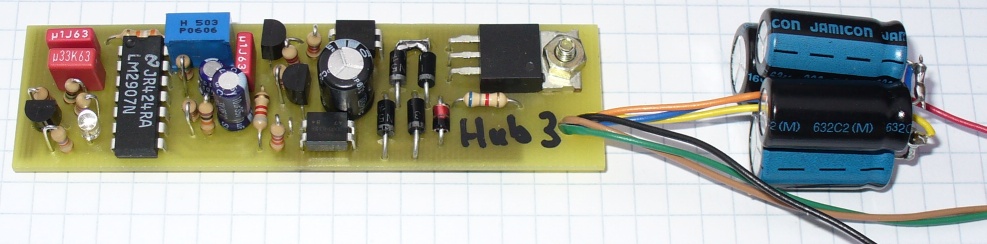
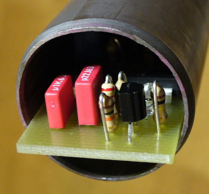
Due to this circuit's complexity, I have made a simple PCB for it. It has been optimized for manual fitting, no SMDs are used. Mechanically, it fits into a 1 1/8" steerer tube with the tuning capacitors C1..4 located off the board (going into the tube first). Smoothing capacitor C5 is meant to go into the headlamp assembly. To learn more about this circuit, download the full documentation and the CAD files (CadSoft Eagle format).
Here are 2 variations of circuit 12. They also sense the dynamo frequency to select b/w voltage doubler and bridge rectifier mode. They were created to avoid the current surge that occurs in circuit 12 when switching from bridge rectifier to voltage doubler mode. These circuits exist on paper only, they have never been built and component values are either a first bet or rightaway missing. I provide these here to share 2 cost-effective ideas of driving a MOSFET when its source potential is continuously changing vs the driver potential (switching of an AC load).
Alternative concept no.1 for an auto-selecting voltage doubler / bridge rectifier. Not tested, component values undetermined. For electronics wizards only.
Alternative concept no.2 for an auto-selecting voltage doubler / bridge rectifier. Not tested, component values undetermined. For electronics wizards only.
Let's move on to an earlier design (bottle dynamo only) that does the automatic mode selection in a slightly different way:
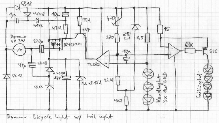
Circuit 13 - a different approach to automatic mode selection
Unlike circuit 12, this one doesn't sense the frequency (speed) but the current driven through the LEDs:
A standard dual OpAmp is being used for measuring the LED current. The other half of the dual OpAmp makes a nice low drop regulator for a tail light (optional).
The optimum transition current is set by the 470R potentiometer. The transition current is just below the point where the doubler output current remains constant while speed increases. Ideally, this alignment is done while the dynamo is at operating temperature (where it delivers a little less current than when it's cold). At the transition point, the circuit alternates between both modes. If the transition point is chosen correctly, both modes yield very similar power at this point so that the transition appears smooth.
The power stage of circuit 13 differs from circuit 12 in a way that it uses a Villiard voltage doubler, not a Greinacher voltage doubler. While this reduces component count and simplifies the circuit, flicker at low speed increases. With a bottle dynamo (this is what circuit 13 has been made for), the flicker is not an issue. With a hub dynamo though it is not acceptable. Now that hub dynamos are becoming dominant, I've decided to retire this circuit.
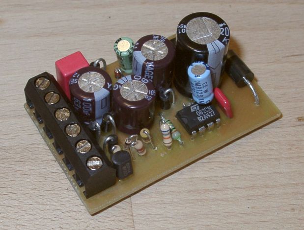
If you like to build circuit 13, I'm not going to stop you. Here's a photo of the assembly, a clean schematic, the PCB and the placement guide. The PCB has been optimized for manual fitting, no SMDs are used. In this version, C07 solders directly to the pins of IC1. Component values have been chosen for 3 white headlight LEDs and 4 red tail light LEDs powered from a Dymotec6 generator.
For the mechanical aspect of your project, take a look at a single LED headlight, a triple-LED headlight and a tail light all built from common parts.
BACK