Electrical Characteristics of Bicycle Dynamos
Summary
Bicycle Dynamos are alternators equipped with permanent magnets. They are typically claw-pole generators and deliver energy at rather low rpm.
The sidewall-running bottle dynamo used to be the most popular type for many years, but today the hub dynamo has taken over. There are a few other types (spoke dynamo, roller dynamo) but those gained limited popularity.
This page focuses on the electrical characteristics of a typical bicycle dynamo and the maximum power that can be extracted from it.
Dynamo Power
In Europe, most bicycle dynamos are rated 3W (that is 500mA at 6V).
For sure, the power of a dynamo light system depends somewhat on the speed. In a standard light system, the power is zero at standstill, at moderate speed it's 3W and at very high speed, it's just a little bit more than 3W. Some manufacturers include limiting zener diodes or other forms of overvoltage protection, to make sure the voltage doesn't rise to levels that kill the light bulb(s).
Test Units
I've tested 3 dynamos (from left to right): Busch + Müller Dymotec6, AXA HR and a cheap one from my local supermarket.
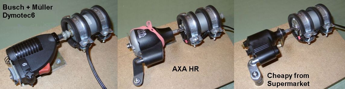
- The B&M Dymotec6 has the best mechanics. It runs very well on the side of the tire. This dynamo is often found on high-quality touring bikes. I paid EUR 24.90 for this (yr 2004).
- The AXA HR has the strongest magnets, it delivers the highest current. It contains 2 zener diodes (BZX 85C 7V5) in series, to limit the output voltage. I had to open the glued plastic enclosure in order to remove these diodes for the measurements. This dynamo is often found on branded bikes. I paid EUR 16.99 for the AXA HR.
- The cheapy from the local supermarket has a magnetic performance slightly inferiour to the Dymotec6. The mechanics are not designed for heavy use but it received all required approvals. It's held together by two screws and can be completely disassembled. This dynamo is usually stock on supermarket bikes. Riders who rarely ride in the dark may like this unit at a bargain price of just EUR 3.45
Tools
For measuring the electrical characteristics of bicycle dynamos, I've created this instrument. It measures the speed of a bike based on the rpm of the dynamo:
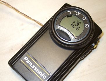 |
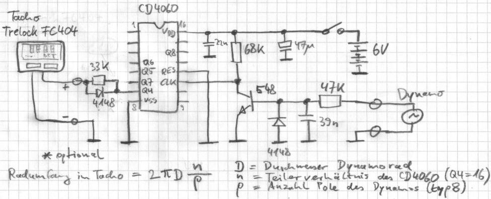
This equiment is built from a Panasonic flashlight and a Trelock FC 404 bicycle computer. It includes additional circuitry (see below) to slice the AC voltage from the dynamo and divide it to a lower frequency that the bicycle computer can handle. Initially, I designed this with a cheap no-name bicycle computer. I soon found that this does some terrible rounding at higher speeds. I switched to a branded item, the Trelock FC 404. It displays the decimals of the speed and it does so correctly. To properly set the wheel circumference in the bicycle computer, it's necessary to know the diameter of the dynamo wheel as well as the number of magnet poles. Most sidewall dynamos have 8 poles - you can feel 8 steps per rotation of the wheel (and measure 4 full sine waves per rotation). Refer to the formula below. |
Other tools used for the measurements below are multimeters, oscilloscope, a lab power supply and an adjustable current sink based on the LM317T linear regulator IC.
Measurements
Maximum Power of different Dynamos
Setup: Dynamo, voltage doubler (Greinacher type using 2x 1N5818 & 2x 1000uF), current sink (variable from 100 to 250 mA). Speedmeter connected to dynamo.
Procedure: Run the dynamo at 15 km/h. Measure the voltage across the current sink for currents 100, 130, 160, 190, 220, 250 mA. Repeat at 40 km/h. Do this for each of the 3 dynamos. Calculate power from voltage and current. Plot power vs load current.
Observation: AXA HR delivers maximum power at 200 mA load current (note this is after voltage doubling !), B&M Dymotec6 at 180 mA, the cheapy at 160 mA. The absolute power levels show the AXA HR on top and the cheapy on the bottom at any speed.
Conclusion: The maximum power is achieved at a specific load current. This depends little on the speed, but mostly on the dynamo. In other words: A dynamo is a current source.
Power vs Speed of Dymotec6
I chose to do this measurement with the Busch & Müller Dymotec6. The nature of the curve is similar for other dynamos, only they would meet a slightly higher or lower power.
Setup: Dymotec6, voltage doubler (Greinacher type using 2x 1N5818 & 2x 1000uF), 180 mA current sink. Speedmeter connected to dynamo.
Procedure: Run the dynamo at 4, 5, 7, 9, 12, 15, 19, 24, 31, 40, 50 km/h and measure the voltage across the current sink. Plot for each speed the calculated power = measured voltage * 180 mA current.
Conclusion: With perfect matching of the load, Dymotec6 delivers 2.7 W at moderate speed, 5 W at high speed and 6 W at really high speed. This is what can be achieved without modification to the dynamo.
Question: Why does a standard 3 W light system with the Dymotec6 not burn out the bulbs at 50 km/h ? This is because at such high speed, the matching of the load is off (current is too high) so that it can't drain maximum power.
Question: Where goes the lost energy when the load doesn't drain the maximum possible power ? It's not lost. The dynamo spins with less effort. Try and short-circuit the dynamo at full speed, the current of the driving motor will drop a lot.
Temperature Performance of Dymotec6
As the dynamo runs for extended periods of time, its temperature increases. This test runs the B+M Dymotec6 at 50 km/h and 23şC ambient temperature. The Greinacher doubler circuit (2x 1N5818 & 2x 1000uF) and a 180 mA load is connected. The power into the load is being monitored. The experiment is stationary on the workbensch, so there's no draught to cool the dynamo. After around 20 minutes, the dynamo output power has decreased from an inital 100% to 80%. For another 10 minutes, it doesn't drop any further. The temperature on the casing of the dynamo measures 89şC at the end of these 30 minutes. It's considerably hotter inside.
Continuing this experiment, a standard 80mm computer fan is mounted to provide some cooling as it would be on a moving bike. The power increases and eventually stabilizes at 89% of the start value. The temperature stabilizes at around 40şC.
The Dymotec6 was chosen for this experiment as it has the best mechanical design of all tested dynamos. It doesn't suffer any noticable deterioration after running at 50 km/h and delivering well above 5 W for 2 hours. A lot of dynamos don't withstand this. Bearings and their lubrication suffer from the high internal temperature, resulting in rapid wear. Once the rotating magnet comes into contact with the stator, friction and internal temperature dramatically increase, the dynamo body melts and eventually the rotor jams. In my setup, this just tears the coupling between motor and dynamo while on a real bike, the dynamo wheel may pop off so that the rotor shaft causes damage to tire, rim or spokes. Bottom line: Avoid using a cheap dynamo to assist the brakes on long descents.
BACK